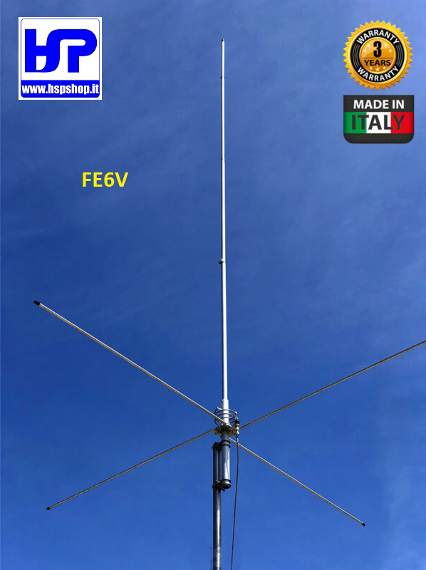
GRAZIOLI - FE6V - 5/8 WAVE VERTICAL ANTENNA - TUNABLE 50-54 MHz (6 METERS BAND) - WEIGHT: 3,34 kg - LENGHT: m 4.17 - POWER: 2 kW
Description
Grazioli FE6V is a 5/8 λ antenna for the 6 meters band.
The goal was to build an extremely robust, high-performance antenna with a low radiation angle, and which could withstand extremely high powers (2 kW CW continuous all-mode).
The result is FE6V, which has unique characteristics compared to the current market and brings together all our experience in the sector.
MATERIALS AND CONSTRUCTION
For our tubes we have used the best material that can be used for the construction of the antennas; it is the aluminium, magnesium and silicon alloy called AW6063-T66, hardened to the T-66 state. It gives the stylus exceptional resistance, which is achieved by extrusion and subsequently by cold drawing.
Our tubular elements are extremely precise on both diameters, and also on the wall thickness, allowing a precise coupling and with the least "play" between the pipes.
The "Ground Plane" is made up of 4 strong radials 1.4 m long, "Full-Quarter Wave" made in a single section with a diameter and thickness of 13×1.25 mm.
The radials are fixed to the support plate by means of two U-Bolts and self-locking nuts in the fixing area.
4 fiberglass reinforcements are supplied which, inserted in the largest part of the tube, strengthen the joints and prevent crushing.
THE CHOICES THAT MAKE THE DIFFERENCE
The "Full-Quarter Wave" RESONANT Ground Plane
Based on our electromagnetic simulations also validated by comparative instrumental tests, with this ground plane, which is widely used for most antennas (from HF to UHF bands) the performance in terms of horizontal angle of maximum radiation or Take-Off they are noticeably better.
We compared two equal 5/8 antennas:
one with GP composed of 8 NON-RESONANT radials of 1/8 wave and one with a GP of 4 RESONANT radials of ¼ wave under the same installation conditions.
The result of our tests is that the version with 4 RESONANT radials ¼ lambda always obtains an angle of maximum radiation or Take-Off of about 4° or 5° lower. This results in a dramatic improvement in long distance DX links.
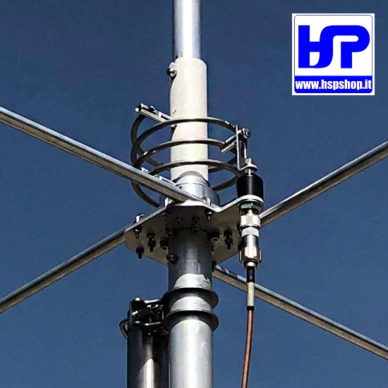
The high "Q" coil
The coil plays a fundamental role for impedance matching and maximum RF transfer, its shape given by the length/diameter ratio, the pitch between the coils, the material and diameter of the wire and the presence or absence of metal cores internally they determine the merit factor "Q" ("Q" = Quality factor).
In simple terms: the higher the "Q" of the coil, the more the losses in high frequency are reduced. We have created a generously sized coil suspended in the air without metal cores, with widely spaced coils, obtaining a "Q" value among the highest ones.
This translates into maximum efficiency, and the ability to withstand high RF power.
NOTE:
The coil is directly connected to direct current (DC-Ground). In this way atmospheric and impulsive disturbances are significantly reduced.
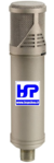
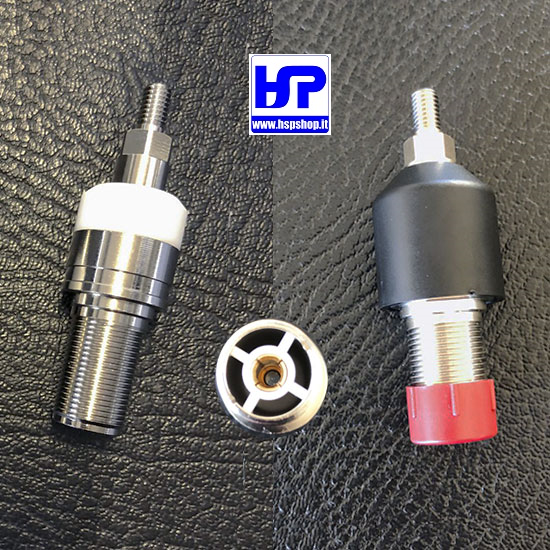
The UHF Connector
The FE10V's connector is not the commercial SO-239 type used by most manufacturers. The connector was designed and manufactured directly by us, has a real impedance of 50 Ohm and can be used up to 500MHz. The goal was to create a reliable connector capable of withstanding 5 kW CW continuous at 30MHz and more than 3 kW at 50 MHz.
The body is made of Nickel plated CW614N brass, while the pin is 24K gold plated to avoid oxidation and equipped with a 4 bar insulator which maintains its centering and elasticity, avoiding loss of contact.
The insulating part is made of PTFE, one of the best insulating materials due to its exceptional electrical (low dielectric constant and reduced loss factor) and thermal (operating temperature from -100° to +260°) qualities. Finally, the connector is protected by a special elastomer cap which prevents infiltration of water and humidity.
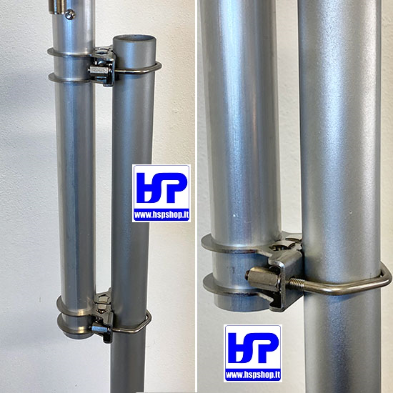
The Anchor Bracket
Made of 2.5 mm thick AISI304 stainless steel. it is fixed to the antenna tube by means of a clamp closing system, creating an extremely robust mechanical block.
The fixing to the mast is made with V-Bolt M6 in AISI304 and column nuts to facilitate tightening.
TECHNICAL DATA
|
Electrical Data
|
|
Mechanical Data
|
|
Antenna Type
|
5/8 λ GP with 4 full ¼ wave radials
|
Materials
|
Aluminnum Alloy AW6063-T66 hard drawn tube, Fiberglass, Brass, PTFE. All hardware are made of SS AISI-304 and 316
|
|
|
|
Frequency Range
|
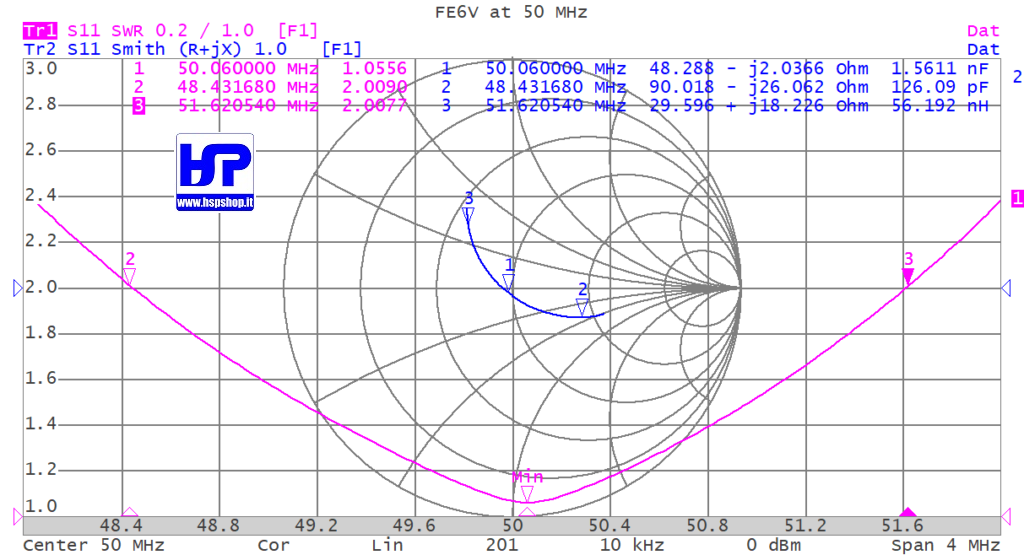
Tunable from 50 to 54 MHz (with Graph)
|
Wind surface area
|
0.16 m2
|
|
|
|
Impedance
|
50Ω Unbalanced
|
Wind load @ 130Km/h
|
15.6 Kgf
|
|
|
|
Radiation Type
|
Omnidirectional
|
Wind survival (no ice)
|
150 Km/h
|
|
|
|
Polarization
|
Linear – Vertical
|
Antenna Height
|
4.17 m @ 50 MHz
|
|
|
|
Gain
|
1.5 dBd – 3.65 dBi
|
Radials length
|
1.4 m (Full quarter wave)
|
|
|
|
Bandwidth @SWR 2:1
|
≥ 3.1 MHz @ 50 MHz
|
Mounting mast bracket
|
ø 40-54 mm
|
|
|
|
SWR @resonance
|
≤1.2:1 @ antenna connector
|
Antenna Net weight
|
3,34 kg
|
|
|
|
Max. Input Power
|
2000 Watt continuos all mode
|
Package dimensions
|
14x14x145 cm
|
|
|
|
Feed system
|
high-Q air wound matching coil, DC-Ground
|
Weight in package
|
4.6 kg
|
|
|
|
Input connector
|
50Ω UHF female PTFE insulator, gold plated pin
|
|
|
|
|
")
")
")


 BELDEN - H155 - 50 OHM COAXIAL CABLE
 BELDEN - H1000 - 50 OHM COAXIAL CABLE
 RG-213/U MIL-C-17F - 50 OHM COAXIAL CABLE
 M&P - AIRBORNE 10 - COAX CABLE 10.3 mm 50 OHM
 M&P - AIRBORNE 5 - COAX CABLE 5 mm 50 OHM
 M&P - EXTRAFLEX BURY 10 - COAX CABLE 10.3 mm
 M&P - HYPERFLEX 10 - COAX CABLE 10.3mm 50 OHM
 M&P - HYPERFLEX 10 SAHARA FT8 - COAX 10.3 mm
 M&P - HYPERFLEX 13 - COAX CABLE 12.7mm 50 OHM
 M&P - HYPERFLEX 5 - COAX CABLE 5.4 mm 50 OHM
 M&P - ULTRAFLEX 7 - COAX CABLE 7.3 mm 50 OHM
 M&P - ULTRAFLEX 7 SAHARA - COAX CABLE 7.3 mm
 AMPHENOL - PL-259 - ORIGINAL CONNECTOR
 UG-176 REDUCER FOR PL-259 or N200 and H155