MUSIC AUDIO RADIO-ELECTRONICS COMPUTER
")
")
")


HOME PAGE RADIO - ELECTRONICS ANTENNAS GRAZIOLI - HW10V - 1/2 WAVE ANTENNA 10-11 M
GRAZIOLI - HW10V - 1/2 WAVE ANTENNA 10-11 M
In stock
Available delivery methods: STANDARD delivery WITH INSURANCE, Pickup by customer in our physical shop, STANDARD DELIVERY IN ITALY, HEAVY (over 10 kg) OR BULKY GOODS - ONLY FOR DESTINATIONS IN ITALY!, HEAVY (over 10 kg) OR BULKY GOODS WITH INSURANCE - ONLY FOR DESTINATIONS IN ITALY!, EUROPE 1 - SMALL PARCEL (UP TO 10 KG) - NO INSURANCE, EUROPE 2 - LARGE / LONG OR OVER 10 KG PARCEL - NO INSURANCE, EUROPE 1 - SMALL PARCEL - (UP TO 10 KG) - WITH INSURANCE, EUROPE 2 - LARGE / LONG OR OVER 10 kg PARCEL - WITH INSURANCE, CORRIERE STANDARD ISOLE MINORI E VENEZIA LAGUNA, CORRIERE MERCE ASSICURATA ISOLE MINORI E VENEZIA LAGUNA (fino a 10 kg)
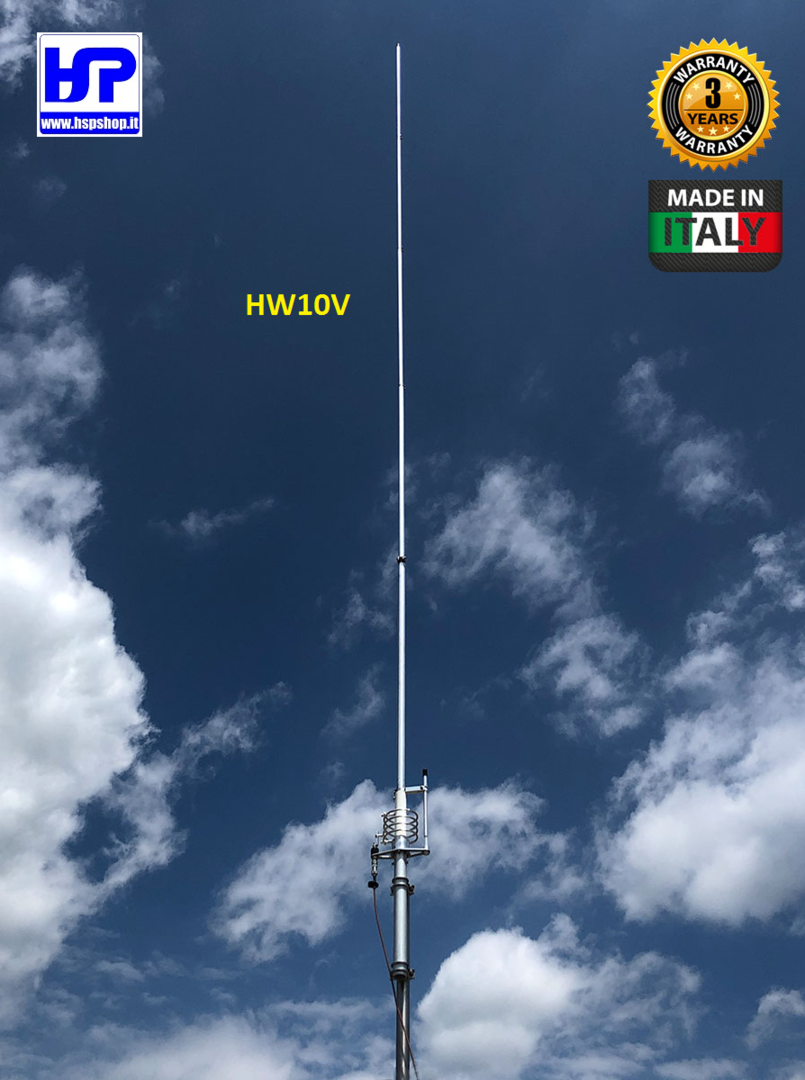


GRAZIOLI - HW10V - 1/2 WAVE VERTICAL ANTENNA -NO RADIALS- TUNABLE 26-30 MHz (11-10 M BAND) - WEIGHT: 3.1 kg - LENGHT: m 5.94 - POWER: 3000 W
Description
1/2 λ vertical antenna fed at the base, adjustable from 26 to 30 MHz by adjusting the length of the rod, and fine tuning at the base by means of a high voltage variable capacitor (40KV) isolated in PTFE.
Extremely robust construction in AW6063-T66 aluminum alloy and details made with CNC from solid.
Supplied with quality 304 and 316 stainless steel hardware for long service without rust.
High applicable input power, up to 3 kW continuous, All-mode.
Detailed assembly manual and serial number that identifies the production batch and construction data.
MATERIALS AND CONSTRUCTION
For our tubes we have used the best alloy that can be used for the construction of the antennas, the AW6063-T66 alloy of aluminium, magnesium and silicon hardened to the T-66 state which gives the stylus exceptional resistance, which is made by extrusion and subsequently cold drawn . Our tubes are extremely accurate on both diameters, and also on the wall thickness, allowing a precise coupling and with less "play" between the tubes.
The sections of the vertical style are divided as follows starting from the bottom:
Anchor tube D.42×2
1st stage above the coil D.29×1.5
2nd stage D.25.5×1.5
3rd stage D.22×1.25
4th stage D.19×1.25
5th stage D.16×1.25
insulator made of white fiberglass D.38 with a thickness of 4.2mm.
THE CHOICES THAT MAKE THE DIFFERENCE
Why build an antenna capable of withstanding continuous power of 3 kW?
Because an antenna that accepts high powers is a more efficient antenna, otherwise it would tend to heat up due to the Joule effect and dissipate a significant part of the applied RF power in heat, which happens with most competing products, but which unfortunately users cannot test due to lack of adequate equipment and instruments.
The high "Q" L-C matching circuit
For this product we have created a special parallel L-C circuit to be able to adapt the high impedance that this type of antenna has when fed to the base. The high Q coil is generously sized, suspended in air without metal cores, with widely spaced coils. The coaxial type variable capacitor (similar to a Gamma Match) placed next to the coil is made with PTFE insulation. It is capable of withstanding extremely high voltages above 40 KV, is not affected by ambient temperature, rain or humidity, and does not heat up if subjected to high powers; in addition it allows a simple and convenient calibration at the base of the antenna.
During the development of the matching circuit we had to carefully adjust both the inductance (L) and the capacitance (C) to obtain a truly efficient, reliable and criticality-free circuit. All these measures translate into high efficiency, and the ability to withstand RF power up to 3 kW continuous all-mode.
NOTE:
The coil is directly connected to direct current (DC-Ground). In this way atmospheric and impulsive disturbances are significantly reduced.
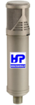
The UHF Connector
The HW10V's connector is not the commercial SO-239 type used by most manufacturers. The connector was designed and manufactured directly by us, has a real impedance of 50 Ohm and can be used up to 500MHz. The goal was to create a reliable connector capable of withstanding 5 kW CW continuous at 30MHz.
The body is made of Nickel plated CW614N brass, while the pin is 24K gold plated to avoid oxidation and equipped with a 4 bar insulator which maintains its centering and elasticity, avoiding loss of contact.
The insulating part is made of PTFE, one of the best insulating materials due to its exceptional electrical (low dielectric constant and reduced loss factor) and thermal (operating temperature from -100° to +260°) qualities. Finally, the connector is protected by a special elastomer cap which prevents infiltration of water and humidity.
The Anchor Bracket
Made of 2.5 mm thick AISI304 stainless steel. it is fixed to the antenna tube by means of a clamp closing system, creating an extremely robust mechanical block.
The fixing to the mast is made with V-Bolt M6 in AISI304 and column nuts to facilitate tightening.
TECHNICAL DATA
|
Electrical Data |
Mechanical Data |
||||
|
Antenna Type |
1/2 λ End Fed Vertical Dipole |
Construction materials |
Aluminnum Alloy AW6063-T66 hard drawn tube, Fiberglass, Brass, PTFE. All hardware are made of SS AISI-304 and 316 |
||
|
Frequency range |
Tunable from 26 to 30 MHz (with Table) |
Wind surface area |
0.195m2 |
||
|
Impedance |
50Ω Unbalanced |
Wind load @ 130Km/h |
19 Kgf |
||
|
Radiation Type |
Omnidirectional |
Wind survival (no ice) |
130 Km/h |
||
|
Polarization |
Linear – Vertical |
Antenna height |
5.94m |
||
|
Gain |
0 dBd – 2,15 dBi |
Radiator length |
5.38 m (Half Wave) |
||
|
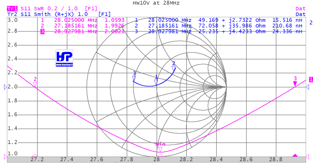
Bandwidth @SWR 2:1 |
≥ 1.7MHz @ 28MHz |
Mounting mast bracket |
ø 40-54 mm |
||
|
SWR @resonance |
≤1.2:1 Typical ≤1.1:1 |
Antenna weight |
3.1 Kg |
||
|
Max. Input Power |
3000 Watt continuous, all mode |
Package dimensions |
14x14x145 cm |
||
|
Feed system |
High “Q” L-C circuit, DC-Ground |
Weight in pack |
4.3 kg |
||
|
Input connector |
50Ω UHF female PTFE insulator, gold plated pin |
||||

Accessories
| Product | Note | Status | Price | |
|---|---|---|---|---|
|
|
1.80 € / m * | ||
|
|
3.60 € / m * | ||
|
|
2.40 € / m * | ||
|
|
3.25 € / m * | ||
|
|
1.35 € / m * | ||
|
|
3.70 € / m * | ||
|
|
3.50 € / m * | ||
|
|
3.70 € / m * | ||
|
|
6.50 € / m * | ||
|
|
1.65 € / m * | ||
|
|
2.20 € / m * | ||
|
|
2.25 € / m * | ||
|
|
6.95 € * | ||
|
|
1.50 € * | ||
|
*
Display accessory details
Prices incl. VAT, plus delivery
|
||||
 BELDEN - H155 - 50 OHM COAXIAL CABLE
 BELDEN - H1000 - 50 OHM COAXIAL CABLE
 RG-213/U MIL-C-17F - 50 OHM COAXIAL CABLE
 M&P - AIRBORNE 10 - COAX CABLE 10.3 mm 50 OHM
 M&P - AIRBORNE 5 - COAX CABLE 5 mm 50 OHM
 M&P - EXTRAFLEX BURY 10 - COAX CABLE 10.3 mm
 M&P - HYPERFLEX 10 - COAX CABLE 10.3mm 50 OHM
 M&P - HYPERFLEX 10 SAHARA FT8 - COAX 10.3 mm
 M&P - HYPERFLEX 13 - COAX CABLE 12.7mm 50 OHM
 M&P - HYPERFLEX 5 - COAX CABLE 5.4 mm 50 OHM
 M&P - ULTRAFLEX 7 - COAX CABLE 7.3 mm 50 OHM
 M&P - ULTRAFLEX 7 SAHARA - COAX CABLE 7.3 mm
 AMPHENOL - PL-259 - ORIGINAL CONNECTOR
 UG-176 REDUCER FOR PL-259 or N200 and H155
Customers who bought this product also bought
 |
 |
 |
 |
 |
 |
Browse these categories as well: ANTENNAS, HF, HF VERTICAL ANTENNAS, CB, CB BASE