MUSIC AUDIO RADIO-ELECTRONICS COMPUTER
")
")
")
* SPECIALS *


*
Prices incl. VAT, plus delivery
HOME PAGE RADIO - ELECTRONICS ANTENNAS BUTTERNUT - HF6V - 10-80 METERS VERTICAL
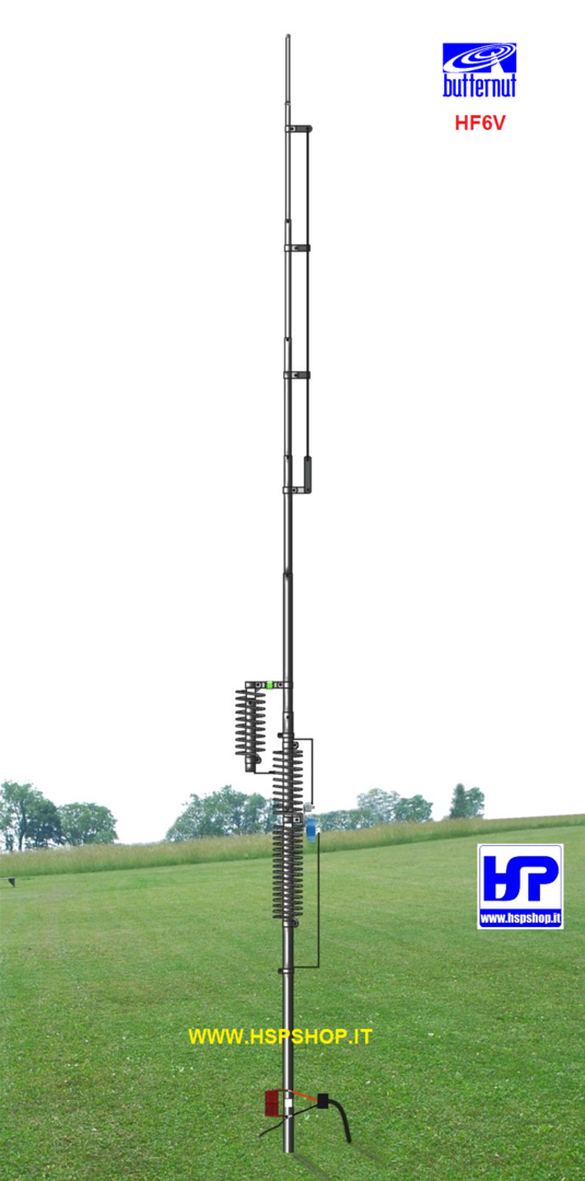
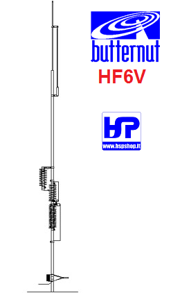
BUTTERNUT - HF6V - 10-80 METERS VERTICAL
Currently unavailable
Notify on availability
Old price 799.00 €
799.00 €
Price incl. VAT, plus delivery
Accessories
| Product | Note | Status | Price | |
|---|---|---|---|---|
|
|
39.00 € * | ||
|
|
36.00 € * | ||
|
|
95.00 € * | ||
|
|
179.00 € * | ||
|
|
229.00 € * | ||
|
|
189.00 € * | ||
|
|
18.00 € * | ||
|
|
79.00 € * | ||
|
|
249.00 € * | ||
|
|
12.50 € * | ||
|
*
Display accessory details
Prices incl. VAT, plus delivery
|
||||
 BUTTERNUT - MPS - MOUNTING POST SLEEVE
 BUTTERNUT - A6 - 6 METER KIT FOR HF-6V
 BUTTERNUT - A-17-12 - 12/17 METERS KIT x HF6V
 BUTTERNUT - STR-II - RADIALS KIT FOR HF
 BUTTERNUT - RMK-II - ROOF MOUNTING KIT
 BUTTERNUT - CPK - COUNTERPOISE KIT
 BUTTERNUT - ANTI-OXIDIZING COMPOUND
 BUTTERNUT - T2 - TRIPOD TOWER FOR ANTENNAS
 BUTTERNUT - TBR-160S - 160 M. RESONATOR KIT
 SELF-BINDING TAPE 25 mm X 10 m BLACK
We also recommend
 |
*
Prices incl. VAT, plus delivery
Customers who bought this product also bought

SELF-BINDING TAPE 25 mm X 10 m BLACK
12.50 €
*
|
 |
 |
*
Prices incl. VAT, plus delivery
Browse these categories as well: ANTENNAS, HF, HF VERTICAL ANTENNAS