MUSIC AUDIO RADIO-ELECTRONICS COMPUTER
")
")
")
* SPECIALS *


*
Prices incl. VAT, plus delivery
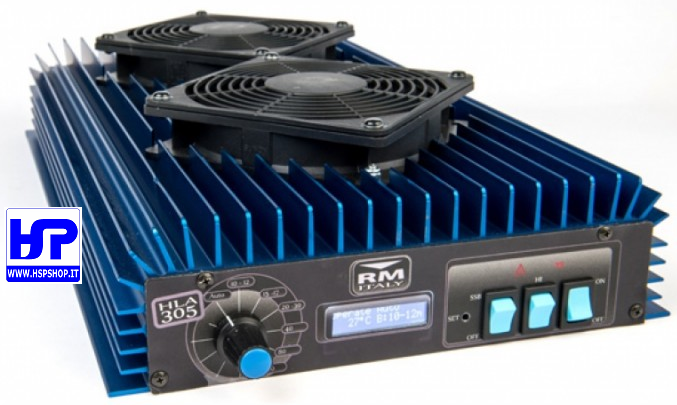
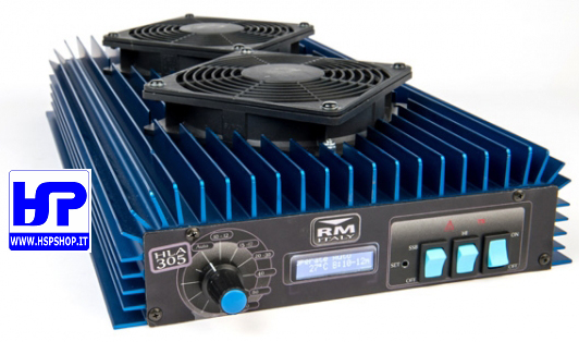
HOME PAGE RADIO - ELECTRONICS LINEAR AMPLIFIERS RM - HLA305V - 1.8-30 MHz 300W AMPLIFIER
RM - HLA305V - 1.8-30 MHz 300W AMPLIFIER
In stock
Old price 1,037.00 €
769.00 €
You save 26 %
Price incl. VAT, plus delivery
Available delivery methods: STANDARD delivery WITH INSURANCE, Pickup by customer in our physical shop, STANDARD DELIVERY IN ITALY, HEAVY (over 10 kg) OR BULKY GOODS - ONLY FOR DESTINATIONS IN ITALY!, HEAVY (over 10 kg) OR BULKY GOODS WITH INSURANCE - ONLY FOR DESTINATIONS IN ITALY!, EUROPE 1 - SMALL PARCEL (UP TO 10 KG) - NO INSURANCE, EUROPE 2 - LARGE / LONG OR OVER 10 KG PARCEL - NO INSURANCE, EUROPE 1 - SMALL PARCEL - (UP TO 10 KG) - WITH INSURANCE, EUROPE 2 - LARGE / LONG OR OVER 10 kg PARCEL - WITH INSURANCE, CORRIERE STANDARD ISOLE MINORI E VENEZIA LAGUNA, CORRIERE MERCE ASSICURATA ISOLE MINORI E VENEZIA LAGUNA (fino a 10 kg)
Accessories
| Product | Note | Status | Price | |
|---|---|---|---|---|
|
|
85.00 € * | ||
|
|
45.00 € * | ||
|
|
273.00 € * | ||
|
|
10.00 € * | ||
|
|
12.00 € * | ||
|
|
14.00 € * | ||
|
|
16.00 € * | ||
|
|
25.00 € * | ||
|
|
27.00 € * | ||
|
*
Display accessory details
Prices incl. VAT, plus delivery
|
||||
 HSP - 35/600 - ANTI-TVI LOW PASS FILTER 1200W
 RM ITALY - 27/586 - ANTI-TVI LOW PASS FILTER
 RM - SPS1050S - POWER SUPPLY - 9-15V 50-55A
 PL-259 JUMPER CABLE - Lenght: 50 cm
 PL-259 JUMPER CABLE - Lenght: 100 cm
 PL-259 JUMPER CABLE - Lenght: 50 cm H155
 PL-259 JUMPER CABLE - Lenght: 100 cm H155
 PL-259 AMPHENOL JUMPER CABLE - L=50 cm H155
 PL-259 AMPHENOL JUMPER CABLE - L=100 cm H155
Browse this category: LINEAR AMPLIFIERS