MUSIC AUDIO RADIO-ELECTRONICS COMPUTER
")
")
")
* SPECIALS *


*
Prices incl. VAT, plus delivery
HOME PAGE RADIO - ELECTRONICS ANTENNAS HF HF WIRE ANTENNAS RADIO WORKS - VRD10 - 10M DIPOLE + VERTICAL
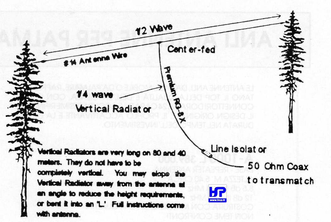
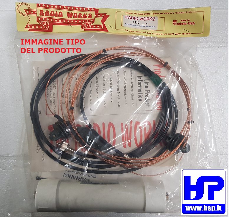
RADIO WORKS - VRD10 - 10M DIPOLE + VERTICAL
In stock
Old price 145.00 €
99.00 €
You save 32 %
Price incl. VAT, plus delivery
Available delivery methods: STANDARD delivery WITH INSURANCE, Pickup by customer in our physical shop, STANDARD DELIVERY IN ITALY, HEAVY (over 10 kg) OR BULKY GOODS - ONLY FOR DESTINATIONS IN ITALY!, HEAVY (over 10 kg) OR BULKY GOODS WITH INSURANCE - ONLY FOR DESTINATIONS IN ITALY!, EUROPE 1 - SMALL PARCEL (UP TO 10 KG) - NO INSURANCE, EUROPE 2 - LARGE / LONG OR OVER 10 KG PARCEL - NO INSURANCE, EUROPE 1 - SMALL PARCEL - (UP TO 10 KG) - WITH INSURANCE, EUROPE 2 - LARGE / LONG OR OVER 10 kg PARCEL - WITH INSURANCE, CORRIERE STANDARD ISOLE MINORI E VENEZIA LAGUNA, CORRIERE MERCE ASSICURATA ISOLE MINORI E VENEZIA LAGUNA (fino a 10 kg)

Accessories
| Product | Note | Status | Price | |
|---|---|---|---|---|
|
|
1.80 € / m * | ||
|
|
2.90 € / m * | ||
|
|
3.60 € / m * | ||
|
|
2.40 € / m * | ||
|
|
6.95 € * | ||
|
|
1.50 € * | ||
|
*
Display accessory details
Prices incl. VAT, plus delivery
|
||||
 BELDEN - H155 - 50 OHM COAXIAL CABLE
 BELDEN - H500 - 50 OHM COAXIAL CABLE
 BELDEN - H1000 - 50 OHM COAXIAL CABLE
 RG-213/U MIL-C-17F - 50 OHM COAXIAL CABLE
 AMPHENOL - PL-259 - ORIGINAL CONNECTOR
 UG-176 REDUCER FOR PL-259 or N200 and H155
Browse this category: HF WIRE ANTENNAS